Thursday, 26 September 2019

Demagnetization


Demagnetization is possible in different ways. One of the most common is to subject the magnetized part to a magnetizing force that continually reverses its direction while it is gradually decreasing in strength. As the decreasing magnetizing force is applied, first in one direction and then in the opposite direction, the residual magnetization of the part is decreased. Generally, a high-intensity demagnetizer is used. The demagnetization is most common but does not demagnetize as deep or complete as a DC step down unit. This decreasing magnetization is accomplished by smaller and smaller hysteresis loops created by the application of decreasing current. A smaller and narrower loop shows lower residual magnetism. All steels have a certain amount of coercive force, making it extremely difficult if not impossible to demagnetize them completely. The only way to completely demagnetize some materials is to heat them to their Curie point or above. Under normal conditions, a part is considered to be satisfactorily demagnetized if, when checked with a field indicator, the magnetic field is below minimum limits. The Code requires demagnetization when the residual field in the part:
Could interfere with subsequent processing or usage such as machining operations where chips will adhere to the surface of the part of the tip of a tool may become magnetized from contact with the magnetized part. Such chips involve in smooth cutting by the tool adversely affecting both finish and tool life. Other reasons to demagnetize would be in cases where residual magnetism:
May interfere with electric arc welding operations. Residual magnetic fields may deflect the arc away from the point at which it should be applied.
May interfere with the functioning of the part itself, after it is placed into service. Magnetized tools, such as milling cutters, hobs, etc., may hold chips and cause rough surfaces, and may even be broken by adherent chips at the cutting edge.
Moving parts, especially in the oil, may hold particles; for instance, on balls or races of ball bearings, or gear teeth causing wear.
capable of holding particles that interfere with later applied coatings such as plating or paint. Demagnetization may not be required where:
Part material is low carbon steel and has low retentivity.
The material consists of structural parts such as weldments, large castings, boilers, etc., where the presence of a residual field would have little or no effect on the proper performance of the part.
The the part is to be subsequently processed or heat-treated and in the process will become heated above its Curie point or about 770 °C (1390°F) for steel.
Apart is to be subsequently re-magnetized in another direction to the same or higher level at which it was originally magnetized as, for example, between the steps of circular and longitudinal magnetizing, for MT purposes.
Tuesday, 17 September 2019

Plasma Spray


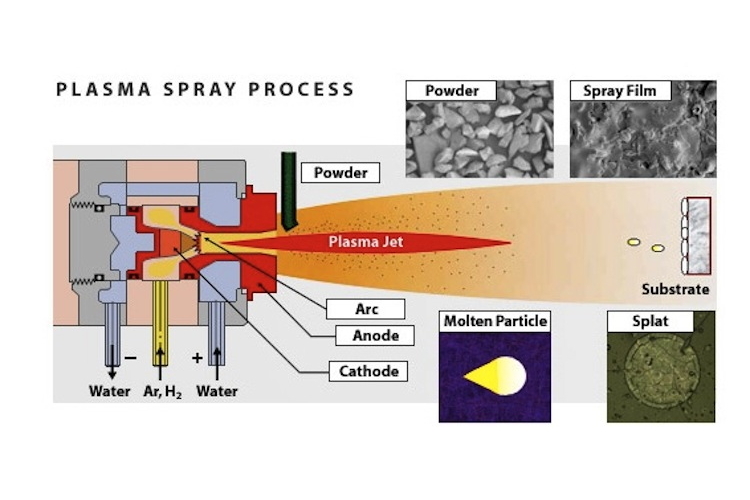
Image result for Plasma SprayA plasma spray torch includes nitrogen, hydrogen, or helium in some cases, is permitted to stream between a water-cooled copper anode and a tungsten cathode. An electric arc is started between the two anodes through a high recurrence release and is then managed to utilize a powder. The arc ionizes the gas, making high-pressure plasma. The subsequent increment in gas temperature, which may surpass 30,000°C, thus expands the gas volume and consequently its pressure and speed as it leaves the nozzle. Gas speed, which may be supersonic, must not be taken as molecule speed. In plasma splash torch the power level range from 30 to 80 kW, reaching as big as 120 kW. Argon is generally picked as the foundation gas because it is chemically inactive and has great ionization qualities. Including the diatomic gasses, hydrogen or nitrogen can build the gas enthalpy. The powder is generally brought into the gas flow either simply outside the light or in a separating way out locale of the nozzle (anode). The powder is warmed and quickened by the high-temperature, high-speed gas plasma flow. Torchworking parameters and design are vital in deciding the speed and temperature achieved by the powder molecules. The working items incorporate not just gas stream, power level, powder feed rate, and bearer gas flow, additionally the separation from the substrate (standoff) to the torch and the deposition angle. The standoff is of significant importance because satisfactory separation must be accommodated warming and quickening the powder, yet excessive separation will permit the powder to cool and lose speed as the gas stream is quite chilling and moderating off. The size and morphology of powder particles affects the rate of warming and speeding up and thus, the effectiveness of testimony and covering quality. As often as possible, a to some degree higher cost for powder with more tightly size appropriation is more than adjusted for by the enhanced deposition effectiveness. Powder speeds as plasma splash deposition range from around 300 to 550 m/s. Temperatures are frequently at the melting point or marginally above. By and large, higher temperatures and molecule speeds over the melting point however without extreme super-heating, yield coverings with the most astounding densities and bond qualities.

Friday, 13 September 2019

Cold Pressure Welding

Image result for Cold Pressure WeldingCold pressure welding is the establishment of an atom-to-atom bond between the two pieces to be joined through intimate contact between oxide-free areas achieved under pressure and without the formation of a liquid phase. So as to develop this bond, surface films have to be removed or at least reduced in amount. Surface films fall into two categories: - Oxide film: All metals except gold possess an oxide film at room temperature. In most metals, the oxide film reaches a limiting thickness in the range 20-100 angstroms at room temperature. - Contaminant film: This film consists of a thin layer of moisture and greases. The best technique, which has proved to be successful in reducing these films, is a combination of chemical and mechanical cleaning. Then, the welding method contains two stages. The process of welding consists of the formation of overlapped oxide-free metallic areas; this is controlled by:
(a) the difference on a micro-scale of the local plastic strain occurring on matching opposite faces of the weld interface
(b) relative hardness of the metal and its oxide film, and
(c) mechanical properties of the oxide.
The second stage involves: 
(a) plastic flow of the metal to the over-lapped areas; the stress at which this can take place is influenced by the stacking fault energy of the metal
(b) some relative shear displacement at the points where metal cleaned of oxide comes into contact; this is influenced by surface roughness Cold pressure welding is used for joining of aluminium cables, various kitchen furniture, electrolysis cells, communication lines, for joining wires and rods, production of heat exchangers at coolers and application of joining different materials nowadays. Various researchers carried some of the studies about cold pressure welding out: gave knowledge about investigations on pressure welding and cold pressure welding. [3] Investigated the mechanism of solid-state pressure welding. Examined the bonding mechanism of cold pressure welding. [5] Investigated cold pressure welding of aluminium and copper by butt upsetting. [6] Investigated effects on welding strength of process parameters in cold pressure welding of aluminium. [7] Obtained the surface roughness depending on welding strength in cold pressure welding of aluminium. [8] Directed the process parameters optimization for obtaining high weld strength in cold solid-state joining of sintered steel and copper powder metallurgical performs. The knowledge about the cold pressure welding method and the developments in its applications were given in this study. Then, as for example, cold pressure welding was applied on commercial purity aluminium alloy sheets as lap welding. 150 metric ton hydraulic press was used for the welding process. Before welding, the wire-brushing process was applied for preparing aluminium sheets, which are test parts, the roughness was determined with surface roughness equipment and afterwards, deformation was applied at different deformation ratios. Then, the microstructure of the welded parts at a given welding deformation was examined, and it was researched that whether joints were properly obtained or not. Then, the results were commented.

Tuesday, 3 September 2019

What is RT?


RT is a volumetric examination method used for examining the entire specimen rather than just the surface. It is the historical approach to examine completed welds for surface and subsurface discontinuities. The method uses the change in absorption of radiation by solid metal and areas of a discontinuity. The radiation transmitted reacts with the film, a latent image is captured, and when the film is processed (developed) creates a permanent image (radiograph) of the weld. Some methods are available which use electronics to create a digital image and are referred to as “filmless.” Due to the hazard of radiation, and the licensing requirements, the cost can be higher and the trained and certified personnel more limited, than with other NDE methods. An NDT examiner interprets and evaluates the radiographs for differences in absorption and transmission results. Radiographic indications show a different density in comparison with the normal background image of the weld or part being inspected. The radiographer also makes sure that the film is exposed by the primary source of the radiation and not backscatter radiation. The NDT examiner that performs the film interpretation, evaluation and reporting should be certified as a minimum to ASNT Level II requirements. However, all personnel performing radiography are required to attend radiation safety training and comply with the applicable regulatory requirements. There are very specific requirements about the quality of the produced radiograph, including the sharpness of the image, the ability to prove adequate film density in the area of interest and sensitivity to the size and type of expected flaws. The requirements include:
  • Method to determine if backscatter is present.
  • Permanent identification, traceable to the component.
  • Film selection under SE-1815.
  • Different designations for hole or wire-type image quality indicators (penetrameters).
  • Suggested radiographic techniques.
  • Facilities for viewing radiographs.

Calibration (certification of source size). The exposure and processing of a radiograph are considered acceptable when it meets the required quality features in terms of sensitivity and density. These factors are designed to ensure that imperfections of a dimension relative to section thickness will be revealed. Standards for industrial radiography require the use of one or more image quality indicators (IQIs) to determine the required sensitivity is achieved. The IQI that was previously known as penetrameter is no longer being used in most codes. To assess sensitivity the required hole or wire as specified by the governing code must be visible on the finished radiograph. Mistakes with IQIs (penetrameters) can have a much greater impact on thinner wall pipe where large root pass imperfections can significantly reduce the strength and integrity of a weld. IQIs (penetrameters) are tools used in industrial radiography to establish the quality level of the radiographic technique