 Gases
used in arc welding processes are the shielding gases. Shielding
gases used in arc welding are argon, helium, and carbon dioxide. The
gases have a remarkable effect on the overall performance of the
welding system. The main function of these gases is to protect the
weld pool from adverse reactions with atmospheric gases. Oxygen,
nitrogen and water vapour present in ambient air can cause weld
contamination. Weld shielding, always involves removal of potentially
reactive gases from the vicinity of the weld, preventing the
detrimental effects on the molten metal of the surrounding
atmosphere. Shielding gases also stabilizes the arc and enhances the
metal transfer mode in arc welding processes. The shielding gas
interacts with the base and filler metal and changes basic mechanical
properties of the weld area, such as strength, toughness, hardness
and corrosion resistance. Shielding gases moreover have important
effects on the formation of the weld bead and the penetration
pattern. The usage of shielding gases can lead to different
penetration and weld bead profiles. However, apart from all these
important effects, the gases have to be handled with care. These
gases that stored in compressed gas cylinders are potentially
hazardous because of the possibility of a sudden release of gas by
removal or breaking off of the valve. High-pressure gas escaping from
such a cylinder causes it to be like a rocket which may smash into
people and properties. In storage, transport and operation of
compressed gas cylinders it is imperative to observe the following
rules: Whether in use or stored, the cylinders should be kept
vertical and secured so as to avoid falling by means of chains and
clamps. To open cylinder valves hammers and wrenches must not be
used. The proper trolley should be used for moving cylinders from one
point to another in the workshop. The cylinder should never be
carried on shoulders because in case it falls it can not only injure
the person but may also explode. Compressed gas should not be exposed
to sunlight or heat as this may lead to an increase in the pressure
leading to an explosion. The temperature of the gas cylinder should
not be allowed to exceed 54 oC. Cylinder valve must be opened
gradually with proper care otherwise it may damage the regulator
diaphragm. Cylinders must have caps during storage and transport.
Gases
used in arc welding processes are the shielding gases. Shielding
gases used in arc welding are argon, helium, and carbon dioxide. The
gases have a remarkable effect on the overall performance of the
welding system. The main function of these gases is to protect the
weld pool from adverse reactions with atmospheric gases. Oxygen,
nitrogen and water vapour present in ambient air can cause weld
contamination. Weld shielding, always involves removal of potentially
reactive gases from the vicinity of the weld, preventing the
detrimental effects on the molten metal of the surrounding
atmosphere. Shielding gases also stabilizes the arc and enhances the
metal transfer mode in arc welding processes. The shielding gas
interacts with the base and filler metal and changes basic mechanical
properties of the weld area, such as strength, toughness, hardness
and corrosion resistance. Shielding gases moreover have important
effects on the formation of the weld bead and the penetration
pattern. The usage of shielding gases can lead to different
penetration and weld bead profiles. However, apart from all these
important effects, the gases have to be handled with care. These
gases that stored in compressed gas cylinders are potentially
hazardous because of the possibility of a sudden release of gas by
removal or breaking off of the valve. High-pressure gas escaping from
such a cylinder causes it to be like a rocket which may smash into
people and properties. In storage, transport and operation of
compressed gas cylinders it is imperative to observe the following
rules: Whether in use or stored, the cylinders should be kept
vertical and secured so as to avoid falling by means of chains and
clamps. To open cylinder valves hammers and wrenches must not be
used. The proper trolley should be used for moving cylinders from one
point to another in the workshop. The cylinder should never be
carried on shoulders because in case it falls it can not only injure
the person but may also explode. Compressed gas should not be exposed
to sunlight or heat as this may lead to an increase in the pressure
leading to an explosion. The temperature of the gas cylinder should
not be allowed to exceed 54 oC. Cylinder valve must be opened
gradually with proper care otherwise it may damage the regulator
diaphragm. Cylinders must have caps during storage and transport.Thursday, 31 October 2019
Gas in Arc welding
Gases
used in arc welding processes are the shielding gases. Shielding
gases used in arc welding are argon, helium, and carbon dioxide. The
gases have a remarkable effect on the overall performance of the
welding system. The main function of these gases is to protect the
weld pool from adverse reactions with atmospheric gases. Oxygen,
nitrogen and water vapour present in ambient air can cause weld
contamination. Weld shielding, always involves removal of potentially
reactive gases from the vicinity of the weld, preventing the
detrimental effects on the molten metal of the surrounding
atmosphere. Shielding gases also stabilizes the arc and enhances the
metal transfer mode in arc welding processes. The shielding gas
interacts with the base and filler metal and changes basic mechanical
properties of the weld area, such as strength, toughness, hardness
and corrosion resistance. Shielding gases moreover have important
effects on the formation of the weld bead and the penetration
pattern. The usage of shielding gases can lead to different
penetration and weld bead profiles. However, apart from all these
important effects, the gases have to be handled with care. These
gases that stored in compressed gas cylinders are potentially
hazardous because of the possibility of a sudden release of gas by
removal or breaking off of the valve. High-pressure gas escaping from
such a cylinder causes it to be like a rocket which may smash into
people and properties. In storage, transport and operation of
compressed gas cylinders it is imperative to observe the following
rules: Whether in use or stored, the cylinders should be kept
vertical and secured so as to avoid falling by means of chains and
clamps. To open cylinder valves hammers and wrenches must not be
used. The proper trolley should be used for moving cylinders from one
point to another in the workshop. The cylinder should never be
carried on shoulders because in case it falls it can not only injure
the person but may also explode. Compressed gas should not be exposed
to sunlight or heat as this may lead to an increase in the pressure
leading to an explosion. The temperature of the gas cylinder should
not be allowed to exceed 54 oC. Cylinder valve must be opened
gradually with proper care otherwise it may damage the regulator
diaphragm. Cylinders must have caps during storage and transport.Wednesday, 23 October 2019
Radiographic Testing
RT
is a volumetric examination method used for examining the entire
specimen rather than just the
surface. It is the historical approach to examine completed welds for surface and subsurface
discontinuities. The change in absorption of radiation by solid metal and in areas of a discontinuity is used in this method. The radiation transmitted reacts with the film, a latent image is captured, and when the film is processed (developed) creates a permanent image (radiograph) of the weld. Some methods also use electronics to create a digital image and are referred to as “filmless.” Due to the hazard of radiation, and the licensing requirements, the cost can be higher and at the same time, the number of trained personnel is limited, than with other NDE methods. An NDT examiner interprets and evaluates the radiographs for differences in absorption and transmission results. Radiographic results display is different as compared with the normal background image of the weld or part being inspected. The radiographer also makes sure that the film is exposed by the primary source of the radiation and not backscatter radiation. The NDT examiner that performs the film interpretation, evaluation and reporting should be certified as a minimum to ASNT Level II requirements. However, all personnel performing radiography are required to attend radiation safety training and comply with the applicable regulatory requirements. There are very specific requirements with regard to the quality of the produced radiograph, including the sharpness of the image, the ability to prove adequate film density in the area of interest and sensitivity to the size and type of expected flaws. Requirements listed in Article 2 include:
a.
Method to determine if backscatter is present.
b. Permanent
identification, traceable to the component.
c. Film selection in
accordance with SE-1815.
d. Designations for a hole or wire-type image
quality indicators.
e. Suggested radiographic techniques.
f.
Facilities for viewing radiographs
g. Calibration (certification of
source size).
The exposure and processing of a radiograph are
considered acceptable when it meets the required quality features in
terms of sensitivity and density. These factors are designed to
ensure that imperfections of a dimension relative to section the thickness will be revealed.
Thursday, 17 October 2019
Mechanical Joints
Threaded joints are the oldest method of joining piping systems. Thread cutting should be regarded as a precision machining operation. Typical threading die. For steel pipe, the lip angle should be about, but for brass, it should be much smaller. Improper lip angle results in rough or torn threads. Since pipe threads are not perfect, joint compounds are used to provide leak tightness. The compounds selected, of course, should be compatible with the fluid carried and should be evaluated for possible detrimental effects on system components. Manufacturers’ recommendations should be followed. Where the presence of a joint compound is undesirable, dry seal pipe threads in accordance with ASME B1.20.346 may be employed. These are primarily found in hydraulic and pneumatic control lines and instruments. Flanged joints are most often used where disassembly for maintenance is desired. A great deal of information regarding the selection of flange types, flange tolerances, facings and gaskets, and bolting is found in B16.5. The limitations regarding cast iron-to-steel flanges, as well as gasket and bolting selection, should be carefully observed. The governing code will usually have further requirements. Gasket surfaces should be carefully cleaned and inspected prior to making up the joint. Damaged or pitted surfaces may leak. Appropriate gaskets and bolting must be used. The flange contact surfaces should be aligned perfectly parallel to each other. Attempting to correct any angular deviation perpendicular to the flange faces while making up the joint may result in overstressing a portion of the bolts and subsequent leakage. The proper gasket should be inserted making sure that it is centred properly on the contact surfaces. Bolts should be tightened hand-tight. If necessary for alignment elsewhere, the advantage may be taken of the bolt hole tolerances to translate or rotate in the plane of the flanges. In no case should rotation perpendicular to the flange faces be attempted? When the assembly is in its final location, bolts should be made up wrench-tight in a staggered sequence. The bolt loading should exert a compressive force of about twice that generated by the internal pressure to compensate not only for internal pressure but for any bending loads which may be imposed on the flange pair during operation. For a greater guarantee against leakage, torque wrenches may be employed to load each bolt or stud to some predetermined value. Care should be exercised to preclude loading beyond the yield point of the bolting. In other cases, special studs that have had the ground of the end to permit micrometre measurement of stud elongation may be used. Flange pairs which are to be insulated should be carefully selected since the effective length of the stud or bolt will expand to a greater degree than the flange thicknesses, and leakage will occur. Thread lubricants should be used, particularly in high-temperature service to permit easier assembly and disassembly for maintenance.
Friday, 11 October 2019
Construction of Pipeline
Designing
and constructing a pipeline is a major undertaking, requiring a wide
variety of engineering and construction skills. A large pipeline the operator would have the internal resources (both trained and
experienced manpower and equipment) to undertake all phases of
pipeline construction, it is more likely that virtually all of the
major phases of construction will be contracted out to companies
possessing the necessary expertise and capacities to complete the
task. While that guarantees the critical requirements of the pipeline
construction will be met, it also introduces the need to control
logistics to ensure that all contractor activities are coordinated
and not mutually exclusive of one another. Construction can take
place because pipeline construction equipment is distributed along
the pipeline route in a moving assembly line in which only one major
item of construction equipment is normally needed at any one point of
time. The distance along the pipeline over which this equipment is
deployed is relatively shorter and less than a mile, but there may be
several sets of construction equipment operational along the pipeline
route at any given time. The complete set of equipment — for
ditching, welding, coating, lowering in, and backfilling are called
spreads. A single pipeline may be built using several spreads,
reducing the overall construction period, but also increasing the number of people and secondary resources required to support them.
Large pipeline projects can also be divided into two or more
segments, and different construction contractors may be used to
install each segment. Various construction activities also take place
simultaneously on a number of segments. Each of these contractors may
field several spreads to build a segment. The actual installation of
the pipeline includes these major steps:
1. clearing the ROW as
needed.
2. Ditching.
3. Stringing pipe joints along the ROW.
4.
Welding the pipe joints together.
5. Applying a coating and wrapping
the exterior of the pipe (except for the portions of the pipe at
each end, which is sometimes coated before being delivered to the job
site).
6. Lowering the pipeline into the ditch.
7. Backfilling the
ditch.
8. Testing the line for leaks.
9. Cleanup and drying the
pipeline after testing to prepare it for operation.
10. Reclaiming
impacted environmental areas.
Thursday, 3 October 2019
Visual Testing
Visual
inspection (VT) refers to the detection of surface imperfections
using the eye. Usually being applied without any kind of additional
equipment, VT can be improved by using aids such as a magnifying
glass to improve its effectiveness and scope. VT is one of the
primary NDT methods. Since it relies on an evaluation made using the
eye, VT is generally considered to be the primary and oldest method
of NDT. Due to the relative simplicity and as it does not require
sophisticated apparatus, it is a very inexpensive method thus
provides an advantage over other NDT methods. VT is an ongoing
inspection that can be applied at various stages of construction. The
primary limitation of VT is it is only capable of evaluating
discontinuities, which can be seen on the surface of the material or
part. On several occasions, there are some visual indications of a
subsurface imperfection that may need an additional NDT method to
provide verification of the subsurface discontinuity. VT is often
taken to be effective when it is performed at all stages of any new
fabrication and is the main method used during the inspection of
pressure equipment. If applied after welding has been completed, it
is possible that subsurface flaws may not be detected. Thus it can be
said that VT will only be fully effective if it is applied throughout
any fabrication or inspection. An effective VT that is applied at the
correct time will detect most defects or discontinuities that may
later be found by some other costly and time-consuming NDT method. A
flaw, such as incomplete fusion at the weld root, can be repaired
easily and quickly right after it is produced, saving on expense and
time required repairing it after the weld has been inspected using
some other NDT technique. VT provides immediate information on the
condition of pressure equipment regarding such things as corrosion,
bulging, distortion, correct parts, failures, etc. VT requires three
basic conditions to be in place. Good vision: to be able to see what
we are looking for, good lighting: the correct type of light is
important & experience: to be able to recognize problems. As
mentioned previously, one of the advantages of VT is that there is
little or no equipment required, which improves its economy or
portability. Equipment so as to improve the accuracy, repeatability,
reliability, and efficiency of VT, include various devices.
Magnifying glasses can also be used for a more detailed look at some
visual feature. As such proper care must be taken to avoid making
erroneous decisions regarding the size or extent of some
discontinuity when its image is magnified.
Thursday, 26 September 2019
Demagnetization
 Demagnetization
is possible in different ways. One of the most common is to subject
the magnetized part to a magnetizing force that continually reverses
its direction while it is gradually decreasing in strength. As the
decreasing magnetizing force is applied, first in one direction and
then in the opposite direction, the residual magnetization of the
part is decreased. Generally, a high-intensity demagnetizer is used.
The demagnetization is most common but does not demagnetize as deep
or complete as a DC step down unit. This decreasing magnetization is
accomplished by smaller and smaller hysteresis loops created by the
application of decreasing current. A smaller and narrower loop shows
lower residual magnetism. All steels have a certain amount of
coercive force, making it extremely difficult if not impossible to
demagnetize them completely. The only way to completely demagnetize
some materials is to heat them to their Curie point or above. Under
normal conditions, a part is considered to be satisfactorily
demagnetized if, when checked with a field indicator, the magnetic
field is below minimum limits. The Code requires demagnetization when
the residual field in the part:
Demagnetization
is possible in different ways. One of the most common is to subject
the magnetized part to a magnetizing force that continually reverses
its direction while it is gradually decreasing in strength. As the
decreasing magnetizing force is applied, first in one direction and
then in the opposite direction, the residual magnetization of the
part is decreased. Generally, a high-intensity demagnetizer is used.
The demagnetization is most common but does not demagnetize as deep
or complete as a DC step down unit. This decreasing magnetization is
accomplished by smaller and smaller hysteresis loops created by the
application of decreasing current. A smaller and narrower loop shows
lower residual magnetism. All steels have a certain amount of
coercive force, making it extremely difficult if not impossible to
demagnetize them completely. The only way to completely demagnetize
some materials is to heat them to their Curie point or above. Under
normal conditions, a part is considered to be satisfactorily
demagnetized if, when checked with a field indicator, the magnetic
field is below minimum limits. The Code requires demagnetization when
the residual field in the part:
• Could
interfere with subsequent processing or usage such as machining
operations where chips will adhere to the surface of the part of the
tip of a tool may become magnetized from contact with the magnetized
part. Such chips involve in smooth cutting by the tool adversely
affecting both finish and tool life. Other reasons to demagnetize
would be in cases where residual magnetism:
• May
interfere with electric arc welding operations. Residual magnetic
fields may deflect the arc away from the point at which it should be
applied.
• May
interfere with the functioning of the part itself, after it is placed
into service. Magnetized tools, such as milling cutters, hobs, etc.,
may hold chips and cause rough surfaces, and may even be broken by
adherent chips at the cutting edge.
• Moving
parts, especially in the oil, may hold particles; for instance, on
balls or races of ball bearings, or gear teeth causing wear.
•capable
of holding particles that interfere with later applied coatings such
as plating or paint. Demagnetization may not be required where:
• Part
material is low carbon steel and has low retentivity.
• The
material consists of structural parts such as weldments, large
castings, boilers, etc., where the presence of a residual field would
have little or no effect on the proper performance of the part.
• The the part is to be subsequently processed or heat-treated and in the
process will become heated above its Curie point or about 770 °C
(1390°F) for steel.
• Apart
is to be subsequently re-magnetized in another direction to the same
or higher level at which it was originally magnetized as, for
example, between the steps of circular and longitudinal magnetizing,
for MT purposes.
Tuesday, 17 September 2019
Plasma Spray
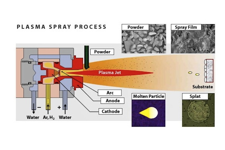 A
plasma spray torch includes nitrogen, hydrogen, or helium in some
cases, is permitted to stream between a water-cooled copper anode
and a tungsten cathode. An electric arc is started between the two
anodes through a high recurrence release and is then managed to
utilize a powder. The arc ionizes the gas, making high-pressure
plasma. The subsequent increment in gas temperature, which may
surpass 30,000°C, thus expands the gas volume and consequently its
pressure and speed as it leaves the nozzle. Gas speed, which may be
supersonic, must not be taken as molecule speed. In plasma splash
torch the power level range from 30 to 80 kW, reaching as big as 120
kW. Argon is generally picked as the foundation gas because it is
chemically inactive and has great ionization qualities. Including the
diatomic gasses, hydrogen or nitrogen can build the gas enthalpy. The
powder is generally brought into the gas flow either simply outside
the light or in a separating way out locale of the nozzle (anode).
The powder is warmed and quickened by the high-temperature,
high-speed gas plasma flow. Torchworking parameters and design are
vital in deciding the speed and temperature achieved by the powder
molecules. The working items incorporate not just gas stream, power
level, powder feed rate, and bearer gas flow, additionally the
separation from the substrate (standoff) to the torch and the
deposition angle. The standoff is of significant importance because
satisfactory separation must be accommodated warming and quickening
the powder, yet excessive separation will permit the powder to cool
and lose speed as the gas stream is quite chilling and moderating
off. The size and morphology of powder particles affects the rate of
warming and speeding up and thus, the effectiveness of testimony and
covering quality. As often as possible, a to some degree higher cost
for powder with more tightly size appropriation is more than adjusted
for by the enhanced deposition effectiveness. Powder speeds as plasma
splash deposition range from around 300 to 550 m/s. Temperatures are
frequently at the melting point or marginally above. By and large,
higher temperatures and molecule speeds over the melting point
however without extreme super-heating, yield coverings with the most
astounding densities and bond qualities.
A
plasma spray torch includes nitrogen, hydrogen, or helium in some
cases, is permitted to stream between a water-cooled copper anode
and a tungsten cathode. An electric arc is started between the two
anodes through a high recurrence release and is then managed to
utilize a powder. The arc ionizes the gas, making high-pressure
plasma. The subsequent increment in gas temperature, which may
surpass 30,000°C, thus expands the gas volume and consequently its
pressure and speed as it leaves the nozzle. Gas speed, which may be
supersonic, must not be taken as molecule speed. In plasma splash
torch the power level range from 30 to 80 kW, reaching as big as 120
kW. Argon is generally picked as the foundation gas because it is
chemically inactive and has great ionization qualities. Including the
diatomic gasses, hydrogen or nitrogen can build the gas enthalpy. The
powder is generally brought into the gas flow either simply outside
the light or in a separating way out locale of the nozzle (anode).
The powder is warmed and quickened by the high-temperature,
high-speed gas plasma flow. Torchworking parameters and design are
vital in deciding the speed and temperature achieved by the powder
molecules. The working items incorporate not just gas stream, power
level, powder feed rate, and bearer gas flow, additionally the
separation from the substrate (standoff) to the torch and the
deposition angle. The standoff is of significant importance because
satisfactory separation must be accommodated warming and quickening
the powder, yet excessive separation will permit the powder to cool
and lose speed as the gas stream is quite chilling and moderating
off. The size and morphology of powder particles affects the rate of
warming and speeding up and thus, the effectiveness of testimony and
covering quality. As often as possible, a to some degree higher cost
for powder with more tightly size appropriation is more than adjusted
for by the enhanced deposition effectiveness. Powder speeds as plasma
splash deposition range from around 300 to 550 m/s. Temperatures are
frequently at the melting point or marginally above. By and large,
higher temperatures and molecule speeds over the melting point
however without extreme super-heating, yield coverings with the most
astounding densities and bond qualities.
Subscribe to:
Posts (Atom)