Friday, 13 December 2019

Attributes of a Welding Inspector


To perform duties in the most effective manner, the welding inspector should be in good physical condition
. Since the primary job involves visual inspection, it is obvious that the welding inspector should have good vision, whether natural or corrected. For instance, if colour or contrast is important to the inspection process being employed (liquid penetrant, magnetic particle, or colour-coded parts) then an individual should be tested for the ability to detect those colours. The AWS Certified Welding Inspector (CWI) program requires a minimum visual acuity and the ability to perceive certain colours, as determined through actual testing. Since welds could be located anywhere on a very large structure, the inspector must be capable of going to the weld at any location in order to make an evaluation. The inspector must comply with safety regulations when performing these duties. The ability of the welding inspector to get to work may be reduced if the inspection is not performed immediately after welding. For example, such aids for the welder as Ladders and scaffolding may be removed, making access impossible or dangerous. Within safety guidelines, the welding inspector should not be prevented from performing a proper inspection because of a physical condition. 

While there may be no specific level of education and training required for welding inspectors, the job may involve interpretation of results. Therefore, an individual must have at least some level of technical knowledge to perform well as an inspector. So as to perform welding inspection, the individuals must make judgments based on visual observations of physical characteristics of welds and weldments and their comparison with drawings or standards. If an individual is unable to understand some written requirements, it will be difficult to make a judgment as to a weld’s acceptability in accordance with that standard. There is more to evaluation than just reading the specifications. Once read, the inspector must interpret its meaning. Even then, some requirement of code or specification may appear very clear and straightforward when initially read; however, comparison of this written requirement with an existing physical condition may still prove to be extremely difficult. Technical ability is also a must to effectively express ideas or inspection findings. In addition, once an inspection has been performed, the inspector must be capable of describing the methods used and subsequent results with sufficient accuracy to adequately communicate to others familiar with the work being performed.

Another quality which the welding inspector should develop is an ability to understand and apply the various documents describing weld requirements. These include, in part: drawings, codes, and specifications. In fact, these documents literally constitute the rules under which the welding inspector must perform. They also state the requirements by which the welding inspector will judge the weld quality. Obviously, such documents must be reviewed prior to the start of any work, because the welding inspector should be aware of the job requirements before any production.

Thursday, 28 November 2019

Future trends in welding

When attempting to forecast future trends in welding technology, it is convenient to differentiate between traditional materials and advanced materials. The properties and functions of traditional materials are well known; therefore, improved performance can be best achieved by reducing the cost increasing the quality of the joining process and through automation and enhanced quality control procedures. The quality of the material depends on the industry considered. Welding structural aluminium is not new in the aerospace industry, yet, it is an advanced application in automotive production. The change to a spaceframe automobile design will remove the structural redundancy afforded by current designs; thus, new joining processes will be required to overcome the limited quality of resistance welding. Brazing as well as laser, or conventional arc welding processes are to handle the fabrication requirements of new automobile structural components. The cost of many advanced materials is so high, and their properties so specialized, that they will only be used where they are essential. Consequently, products will contain more joints, a greater number of which will join dissimilar materials. Few traditional joining processes are practical in this situation; new part designs and joining processes will be required. Adhesives can always be used, but joint properties often place severe limitations on part design or function. Brazing is considered, especially to join ceramics and metal-matrix composites. Low-temperature metallic bonding using transient liquid- phase technology will probably be extended to many more alloy systems. In the brazing process, a component of the brazing material or solder diffuses into the base material resulting in isothermal solidification of the filler material. For every new material developed, joining processes must be restudied or developed to use the material effectively. Use of new materials will be limited by the capability to exploit the joining processes, rather than by the ability to design or produce such materials. The present direction of improvement of welded structures is a decrease in their weight and energy requirement in fabrication, and improvement of consistency and endurance. High strength low-alloy (HSLA) steels are the Centre of application that widening the advances in this direction. The fabrication of structures from HSLA steels without preheating is one of the main problems in arc welding. The results of researches into the problem of hydrogen welded joints have been generalized. The main tendencies of the optimization of properties of HSLA steels are i) the decrease in the content of alloying elements, ii) an increase in the number of combinations of microalloying elements, iii) a decrease in the content of carbon, hydrogen, nitrogen, oxygen, residual elements, sulphur and phosphorus, iv) an improvement of the homogeneity and the level of mechanical properties and improvement of the formability, weldability and toughness of welded joints.

Thursday, 21 November 2019

Attributes of a Welding Inspector


There are many types of welding inspectors, depending upon technical requirements for the particular fabrication process or processes. These include destructive testing specialists, nondestructive examination specialists, code inspectors, military inspectors, and owner’s representative inspectors. All of these may consider themselves welding inspectors simply because they do inspect welds. The fact that welding inspectors work in many different industries performing so many quality-related tasks makes it difficult to clearly and concisely describe what a welding inspector is and how that job function is specifically performed. One fundamental complication is that an individual may perform many functions or only a single function. For example, it is common to perform numerous aspects of welding quality control (e.g., welding procedure qualification, welder qualification, in-process and final visual examination, destructive testing, and final nondestructive examination). However, it is also common for an individual involved in welding inspection to perform only one of those tasks (e.g., a non-destructive examination specialist).To Perform duties effectively, the welding inspector must be in good physical condition. Since the primary job involves visual inspection, it is obvious that the welding inspector should have good vision, whether natural or corrected. For instance, if colour or contrast is important to the inspection process being employed (liquid penetrant, magnetic particle, or colour coded parts) then an individual should be tested for the ability to detect those colours. The AWS Certified Welding Inspector (CWI) program requires a minimum 20/40 visual acuity and the ability to perceive certain colours as determined through actual testing. Physical conditioning also involves the size of some welded structures. Since welds could be located anywhere on a very large structure, the inspector must be capable of going to the weld at any location to make an evaluation. The inspector must comply with safety regulations when performing these duties. The ability of the welding inspector to get to the work may be reduced if the inspection is not performed immediately after welding. For example, such aids for the welder as ladders and scaffolding may be removed, making access impossible or dangerous. Within safety guidelines, the welding inspector should not be prevented from performing a proper inspection because of a physical condition. Technical ability is also necessary for the welding inspector to express ideas or inspection findings effectively. Also, once an inspection has been performed, the inspector must be capable of describing the methods used and subsequent results with sufficient accuracy to adequately communicate to others familiar with the work being performed.

Thursday, 14 November 2019

Welding process


Choosing the right machine is just as important as a technique in welding. The type of welding you purchase should be suited to the specific functions you need it for because there is no such thing as a “one size fits all” welding machine. Weighing the pros and cons of the different welding processes and the projects you are most likely going to use your welder for, is essential to making your selection. People think that there is no single welding process suitable for all welding situations. What’s important is understanding which process is best suited to your application. The most common welding processes include:

 Metal Inert Gas (MIG),
 Tungsten Inert Gas (TIG),
 Flux-Cored Arc Welding ((FCAW),
 Manual Metal Arc Welding (MMAW) often referred to as ‘Stick’ welding;

Each of which has its own set of benefits and limitations. As such there are several factors that
must be considered to determine which welding machine will be the most appropriate for your needs. These include:

 Type of material being welded
 Thickness of material
 Required weld metallurgy
 Welding position
 Available power supply, for example, single-phase or three-phase
 Amount of available current
 Time requirements

Arc welding is a specialized type of welding that uses electricity to join two metal components and
includes sub-types such as gas metal arc welding and plasma arc welding. The reason for its growing popularity is the rising awareness regarding its inherent advantages. For example, due to high heat concentration, arc welding speeds up the welding process, saving both time and energy. This also leads to fewer distortions in the finished product. Furthermore, this type of welding does not entail any extra costs and does not swell the cost of production. Lastly, arc welding has a higher safety quotient as it produces less smoke, which is usually hazardous to human health. Thus, these advantages of this welding process will augur well for the market and its development during the forecast period.

Wednesday, 6 November 2019

Attributes of a welding inspector


To perform duties in the most effective manner, the welding inspector should be in good physical condition. Since the primary job involves visual inspection, it is obvious that the welding inspector should have good vision, whether natural or corrected. For instance, if colour or contrast is important to the inspection process being employed (liquid penetrant, magnetic particle, or colour coded parts) then an individual should be tested for the ability to detect those colours. The AWS Certified Welding Inspector (CWI) program requires a minimum 20/40 visual acuity and the ability to perceive certain colours, as determined through actual testing. Another aspect of physical conditioning involves the size of some welded structures. Since welds could be located anywhere on a very large structure, the inspector must be capable of going to the weld at any location in order to make an evaluation. The inspector must comply with safety regulations when performing these duties. The ability of the welding inspector to get to the work may be reduced if the inspection is not performed immediately after welding. For example, such aids for the welder. As ladders and scaffolding may be removed, making access impossible or dangerous. Within safety guidelines, the welding inspector should not be prevented from performing a proper inspection because of a physical condition. While there may be no specific level of education and training required for welding inspectors, the job may involve interpretation of results. Therefore, an individual must have at least some level of technical knowledge to perform well as an inspector. In order to perform welding inspection, the individual will continually be asked to make judgments based on visual observations of physical characteristics of welds and weldments and their comparison with drawings or standards. If an individual is unable to understand some written requirement, it will be difficult to make a judgment as to a weld’s acceptability in accordance with that standard. There is more to evaluation than just reading the specifications. Once read, the inspector must interpret its meaning. Even then, some requirement of code or specification may appear very clear and straightforward when initially read; however, comparison of this written requirement with an existing physical the condition may still prove to be extremely difficult. Technical ability is also necessary in order for the welding inspector to effectively express ideas or inspection findings. In addition, once an inspection has been performed, the inspector must be capable of describing the methods used and subsequent results with sufficient accuracy to adequately communicate to others familiar with the work being performed.

Thursday, 31 October 2019

Gas in Arc welding


Gases used in arc welding processes are the shielding gases. Shielding gases used in arc welding are argon, helium, and carbon dioxide. The gases have a remarkable effect on the overall performance of the welding system. The main function of these gases is to protect the weld pool from adverse reactions with atmospheric gases. Oxygen, nitrogen and water vapour present in ambient air can cause weld contamination. Weld shielding, always involves removal of potentially reactive gases from the vicinity of the weld, preventing the detrimental effects on the molten metal of the surrounding atmosphere. Shielding gases also stabilizes the arc and enhances the metal transfer mode in arc welding processes. The shielding gas interacts with the base and filler metal and changes basic mechanical properties of the weld area, such as strength, toughness, hardness and corrosion resistance. Shielding gases moreover have important effects on the formation of the weld bead and the penetration pattern. The usage of shielding gases can lead to different penetration and weld bead profiles. However, apart from all these important effects, the gases have to be handled with care. These gases that stored in compressed gas cylinders are potentially hazardous because of the possibility of a sudden release of gas by removal or breaking off of the valve. High-pressure gas escaping from such a cylinder causes it to be like a rocket which may smash into people and properties. In storage, transport and operation of compressed gas cylinders it is imperative to observe the following rules: Whether in use or stored, the cylinders should be kept vertical and secured so as to avoid falling by means of chains and clamps. To open cylinder valves hammers and wrenches must not be used. The proper trolley should be used for moving cylinders from one point to another in the workshop. The cylinder should never be carried on shoulders because in case it falls it can not only injure the person but may also explode. Compressed gas should not be exposed to sunlight or heat as this may lead to an increase in the pressure leading to an explosion. The temperature of the gas cylinder should not be allowed to exceed 54 oC. Cylinder valve must be opened gradually with proper care otherwise it may damage the regulator diaphragm. Cylinders must have caps during storage and transport.

Wednesday, 23 October 2019

Radiographic Testing


RT is a volumetric examination method used for examining the entire specimen rather than just the
surface. It is the historical approach to examine completed welds for surface and subsurface
discontinuities. The change in absorption of radiation by solid metal and in areas of a discontinuity is used in this method. The radiation transmitted reacts with the film, a latent image is captured, and when the film is processed (developed) creates a permanent image (radiograph) of the weld. Some methods also use electronics to create a digital image and are referred to as “filmless.” Due to the hazard of radiation, and the licensing requirements, the cost can be higher and at the same time, the number of trained personnel is limited, than with other NDE methods. An NDT examiner interprets and evaluates the radiographs for differences in absorption and transmission results. Radiographic results display is different as compared with the normal background image of the weld or part being inspected. The radiographer also makes sure that the film is exposed by the primary source of the radiation and not backscatter radiation. The NDT examiner that performs the film interpretation, evaluation and reporting should be certified as a minimum to ASNT Level II requirements. However, all personnel performing radiography are required to attend radiation safety training and comply with the applicable regulatory requirements. There are very specific requirements with regard to the quality of the produced radiograph, including the sharpness of the image, the ability to prove adequate film density in the area of interest and sensitivity to the size and type of expected flaws. Requirements listed in Article 2 include:

a. Method to determine if backscatter is present. 
b. Permanent identification, traceable to the component. 
c. Film selection in accordance with SE-1815. 
d. Designations for a hole or wire-type image quality indicators. 
e. Suggested radiographic techniques.
f. Facilities for viewing radiographs
g. Calibration (certification of source size).

The exposure and processing of a radiograph are considered acceptable when it meets the required quality features in terms of sensitivity and density. These factors are designed to ensure that imperfections of a dimension relative to section the thickness will be revealed.

Thursday, 17 October 2019

Mechanical Joints

Threaded joints are the oldest method of joining piping systems. Thread cutting should be regarded as a precision machining operation. Typical threading die. For steel pipe, the lip angle should be about, but for brass, it should be much smaller. Improper lip angle results in rough or torn threads. Since pipe threads are not perfect, joint compounds are used to provide leak tightness. The compounds selected, of course, should be compatible with the fluid carried and should be evaluated for possible detrimental effects on system components. Manufacturers’ recommendations should be followed. Where the presence of a joint compound is undesirable, dry seal pipe threads in accordance with ASME B1.20.346 may be employed. These are primarily found in hydraulic and pneumatic control lines and instruments. Flanged joints are most often used where disassembly for maintenance is desired. A great deal of information regarding the selection of flange types, flange tolerances, facings and gaskets, and bolting is found in B16.5. The limitations regarding cast iron-to-steel flanges, as well as gasket and bolting selection, should be carefully observed. The governing code will usually have further requirements. Gasket surfaces should be carefully cleaned and inspected prior to making up the joint. Damaged or pitted surfaces may leak. Appropriate gaskets and bolting must be used. The flange contact surfaces should be aligned perfectly parallel to each other. Attempting to correct any angular deviation perpendicular to the flange faces while making up the joint may result in overstressing a portion of the bolts and subsequent leakage. The proper gasket should be inserted making sure that it is centred properly on the contact surfaces. Bolts should be tightened hand-tight. If necessary for alignment elsewhere, the advantage may be taken of the bolt hole tolerances to translate or rotate in the plane of the flanges. In no case should rotation perpendicular to the flange faces be attempted? When the assembly is in its final location, bolts should be made up wrench-tight in a staggered sequence. The bolt loading should exert a compressive force of about twice that generated by the internal pressure to compensate not only for internal pressure but for any bending loads which may be imposed on the flange pair during operation. For a greater guarantee against leakage, torque wrenches may be employed to load each bolt or stud to some predetermined value. Care should be exercised to preclude loading beyond the yield point of the bolting. In other cases, special studs that have had the ground of the end to permit micrometre measurement of stud elongation may be used. Flange pairs which are to be insulated should be carefully selected since the effective length of the stud or bolt will expand to a greater degree than the flange thicknesses, and leakage will occur. Thread lubricants should be used, particularly in high-temperature service to permit easier assembly and disassembly for maintenance.

Friday, 11 October 2019

Construction of Pipeline

Designing and constructing a pipeline is a major undertaking, requiring a wide variety of engineering and construction skills. A large pipeline the operator would have the internal resources (both trained and experienced manpower and equipment) to undertake all phases of pipeline construction, it is more likely that virtually all of the major phases of construction will be contracted out to companies possessing the necessary expertise and capacities to complete the task. While that guarantees the critical requirements of the pipeline construction will be met, it also introduces the need to control logistics to ensure that all contractor activities are coordinated and not mutually exclusive of one another. Construction can take place because pipeline construction equipment is distributed along the pipeline route in a moving assembly line in which only one major item of construction equipment is normally needed at any one point of time. The distance along the pipeline over which this equipment is deployed is relatively shorter and less than a mile, but there may be several sets of construction equipment operational along the pipeline route at any given time. The complete set of equipment — for ditching, welding, coating, lowering in, and backfilling are called spreads. A single pipeline may be built using several spreads, reducing the overall construction period, but also increasing the number of people and secondary resources required to support them. Large pipeline projects can also be divided into two or more segments, and different construction contractors may be used to install each segment. Various construction activities also take place simultaneously on a number of segments. Each of these contractors may field several spreads to build a segment. The actual installation of the pipeline includes these major steps: 
1. clearing the ROW as needed.
2. Ditching.
3. Stringing pipe joints along the ROW.
4. Welding the pipe joints together.
5. Applying a coating and wrapping the exterior of the pipe (except for the portions of the pipe at each end, which is sometimes coated before being delivered to the job site).
6. Lowering the pipeline into the ditch.
7. Backfilling the ditch.
8. Testing the line for leaks.
9. Cleanup and drying the pipeline after testing to prepare it for operation.
10. Reclaiming impacted environmental areas.

Thursday, 3 October 2019

Visual Testing


Visual inspection (VT) refers to the detection of surface imperfections using the eye. Usually being applied without any kind of additional equipment, VT can be improved by using aids such as a magnifying glass to improve its effectiveness and scope. VT is one of the primary NDT methods. Since it relies on an evaluation made using the eye, VT is generally considered to be the primary and oldest method of NDT. Due to the relative simplicity and as it does not require sophisticated apparatus, it is a very inexpensive method thus provides an advantage over other NDT methods. VT is an ongoing inspection that can be applied at various stages of construction. The primary limitation of VT is it is only capable of evaluating discontinuities, which can be seen on the surface of the material or part. On several occasions, there are some visual indications of a subsurface imperfection that may need an additional NDT method to provide verification of the subsurface discontinuity. VT is often taken to be effective when it is performed at all stages of any new fabrication and is the main method used during the inspection of pressure equipment. If applied after welding has been completed, it is possible that subsurface flaws may not be detected. Thus it can be said that VT will only be fully effective if it is applied throughout any fabrication or inspection. An effective VT that is applied at the correct time will detect most defects or discontinuities that may later be found by some other costly and time-consuming NDT method. A flaw, such as incomplete fusion at the weld root, can be repaired easily and quickly right after it is produced, saving on expense and time required repairing it after the weld has been inspected using some other NDT technique. VT provides immediate information on the condition of pressure equipment regarding such things as corrosion, bulging, distortion, correct parts, failures, etc. VT requires three basic conditions to be in place. Good vision: to be able to see what we are looking for, good lighting: the correct type of light is important & experience: to be able to recognize problems. As mentioned previously, one of the advantages of VT is that there is little or no equipment required, which improves its economy or portability. Equipment so as to improve the accuracy, repeatability, reliability, and efficiency of VT, include various devices. Magnifying glasses can also be used for a more detailed look at some visual feature. As such proper care must be taken to avoid making erroneous decisions regarding the size or extent of some discontinuity when its image is magnified.

Thursday, 26 September 2019

Demagnetization


Demagnetization is possible in different ways. One of the most common is to subject the magnetized part to a magnetizing force that continually reverses its direction while it is gradually decreasing in strength. As the decreasing magnetizing force is applied, first in one direction and then in the opposite direction, the residual magnetization of the part is decreased. Generally, a high-intensity demagnetizer is used. The demagnetization is most common but does not demagnetize as deep or complete as a DC step down unit. This decreasing magnetization is accomplished by smaller and smaller hysteresis loops created by the application of decreasing current. A smaller and narrower loop shows lower residual magnetism. All steels have a certain amount of coercive force, making it extremely difficult if not impossible to demagnetize them completely. The only way to completely demagnetize some materials is to heat them to their Curie point or above. Under normal conditions, a part is considered to be satisfactorily demagnetized if, when checked with a field indicator, the magnetic field is below minimum limits. The Code requires demagnetization when the residual field in the part:
Could interfere with subsequent processing or usage such as machining operations where chips will adhere to the surface of the part of the tip of a tool may become magnetized from contact with the magnetized part. Such chips involve in smooth cutting by the tool adversely affecting both finish and tool life. Other reasons to demagnetize would be in cases where residual magnetism:
May interfere with electric arc welding operations. Residual magnetic fields may deflect the arc away from the point at which it should be applied.
May interfere with the functioning of the part itself, after it is placed into service. Magnetized tools, such as milling cutters, hobs, etc., may hold chips and cause rough surfaces, and may even be broken by adherent chips at the cutting edge.
Moving parts, especially in the oil, may hold particles; for instance, on balls or races of ball bearings, or gear teeth causing wear.
capable of holding particles that interfere with later applied coatings such as plating or paint. Demagnetization may not be required where:
Part material is low carbon steel and has low retentivity.
The material consists of structural parts such as weldments, large castings, boilers, etc., where the presence of a residual field would have little or no effect on the proper performance of the part.
The the part is to be subsequently processed or heat-treated and in the process will become heated above its Curie point or about 770 °C (1390°F) for steel.
Apart is to be subsequently re-magnetized in another direction to the same or higher level at which it was originally magnetized as, for example, between the steps of circular and longitudinal magnetizing, for MT purposes.

Tuesday, 17 September 2019

Plasma Spray


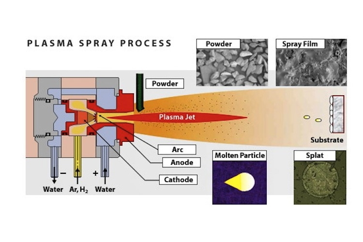
Image result for Plasma SprayA plasma spray torch includes nitrogen, hydrogen, or helium in some cases, is permitted to stream between a water-cooled copper anode and a tungsten cathode. An electric arc is started between the two anodes through a high recurrence release and is then managed to utilize a powder. The arc ionizes the gas, making high-pressure plasma. The subsequent increment in gas temperature, which may surpass 30,000°C, thus expands the gas volume and consequently its pressure and speed as it leaves the nozzle. Gas speed, which may be supersonic, must not be taken as molecule speed. In plasma splash torch the power level range from 30 to 80 kW, reaching as big as 120 kW. Argon is generally picked as the foundation gas because it is chemically inactive and has great ionization qualities. Including the diatomic gasses, hydrogen or nitrogen can build the gas enthalpy. The powder is generally brought into the gas flow either simply outside the light or in a separating way out locale of the nozzle (anode). The powder is warmed and quickened by the high-temperature, high-speed gas plasma flow. Torchworking parameters and design are vital in deciding the speed and temperature achieved by the powder molecules. The working items incorporate not just gas stream, power level, powder feed rate, and bearer gas flow, additionally the separation from the substrate (standoff) to the torch and the deposition angle. The standoff is of significant importance because satisfactory separation must be accommodated warming and quickening the powder, yet excessive separation will permit the powder to cool and lose speed as the gas stream is quite chilling and moderating off. The size and morphology of powder particles affects the rate of warming and speeding up and thus, the effectiveness of testimony and covering quality. As often as possible, a to some degree higher cost for powder with more tightly size appropriation is more than adjusted for by the enhanced deposition effectiveness. Powder speeds as plasma splash deposition range from around 300 to 550 m/s. Temperatures are frequently at the melting point or marginally above. By and large, higher temperatures and molecule speeds over the melting point however without extreme super-heating, yield coverings with the most astounding densities and bond qualities.

Friday, 13 September 2019

Cold Pressure Welding

Image result for Cold Pressure WeldingCold pressure welding is the establishment of an atom-to-atom bond between the two pieces to be joined through intimate contact between oxide-free areas achieved under pressure and without the formation of a liquid phase. So as to develop this bond, surface films have to be removed or at least reduced in amount. Surface films fall into two categories: - Oxide film: All metals except gold possess an oxide film at room temperature. In most metals, the oxide film reaches a limiting thickness in the range 20-100 angstroms at room temperature. - Contaminant film: This film consists of a thin layer of moisture and greases. The best technique, which has proved to be successful in reducing these films, is a combination of chemical and mechanical cleaning. Then, the welding method contains two stages. The process of welding consists of the formation of overlapped oxide-free metallic areas; this is controlled by:
(a) the difference on a micro-scale of the local plastic strain occurring on matching opposite faces of the weld interface
(b) relative hardness of the metal and its oxide film, and
(c) mechanical properties of the oxide.
The second stage involves: 
(a) plastic flow of the metal to the over-lapped areas; the stress at which this can take place is influenced by the stacking fault energy of the metal
(b) some relative shear displacement at the points where metal cleaned of oxide comes into contact; this is influenced by surface roughness Cold pressure welding is used for joining of aluminium cables, various kitchen furniture, electrolysis cells, communication lines, for joining wires and rods, production of heat exchangers at coolers and application of joining different materials nowadays. Various researchers carried some of the studies about cold pressure welding out: gave knowledge about investigations on pressure welding and cold pressure welding. [3] Investigated the mechanism of solid-state pressure welding. Examined the bonding mechanism of cold pressure welding. [5] Investigated cold pressure welding of aluminium and copper by butt upsetting. [6] Investigated effects on welding strength of process parameters in cold pressure welding of aluminium. [7] Obtained the surface roughness depending on welding strength in cold pressure welding of aluminium. [8] Directed the process parameters optimization for obtaining high weld strength in cold solid-state joining of sintered steel and copper powder metallurgical performs. The knowledge about the cold pressure welding method and the developments in its applications were given in this study. Then, as for example, cold pressure welding was applied on commercial purity aluminium alloy sheets as lap welding. 150 metric ton hydraulic press was used for the welding process. Before welding, the wire-brushing process was applied for preparing aluminium sheets, which are test parts, the roughness was determined with surface roughness equipment and afterwards, deformation was applied at different deformation ratios. Then, the microstructure of the welded parts at a given welding deformation was examined, and it was researched that whether joints were properly obtained or not. Then, the results were commented.

Tuesday, 3 September 2019

What is RT?


RT is a volumetric examination method used for examining the entire specimen rather than just the surface. It is the historical approach to examine completed welds for surface and subsurface discontinuities. The method uses the change in absorption of radiation by solid metal and areas of a discontinuity. The radiation transmitted reacts with the film, a latent image is captured, and when the film is processed (developed) creates a permanent image (radiograph) of the weld. Some methods are available which use electronics to create a digital image and are referred to as “filmless.” Due to the hazard of radiation, and the licensing requirements, the cost can be higher and the trained and certified personnel more limited, than with other NDE methods. An NDT examiner interprets and evaluates the radiographs for differences in absorption and transmission results. Radiographic indications show a different density in comparison with the normal background image of the weld or part being inspected. The radiographer also makes sure that the film is exposed by the primary source of the radiation and not backscatter radiation. The NDT examiner that performs the film interpretation, evaluation and reporting should be certified as a minimum to ASNT Level II requirements. However, all personnel performing radiography are required to attend radiation safety training and comply with the applicable regulatory requirements. There are very specific requirements about the quality of the produced radiograph, including the sharpness of the image, the ability to prove adequate film density in the area of interest and sensitivity to the size and type of expected flaws. The requirements include:
  • Method to determine if backscatter is present.
  • Permanent identification, traceable to the component.
  • Film selection under SE-1815.
  • Different designations for hole or wire-type image quality indicators (penetrameters).
  • Suggested radiographic techniques.
  • Facilities for viewing radiographs.

Calibration (certification of source size). The exposure and processing of a radiograph are considered acceptable when it meets the required quality features in terms of sensitivity and density. These factors are designed to ensure that imperfections of a dimension relative to section thickness will be revealed. Standards for industrial radiography require the use of one or more image quality indicators (IQIs) to determine the required sensitivity is achieved. The IQI that was previously known as penetrameter is no longer being used in most codes. To assess sensitivity the required hole or wire as specified by the governing code must be visible on the finished radiograph. Mistakes with IQIs (penetrameters) can have a much greater impact on thinner wall pipe where large root pass imperfections can significantly reduce the strength and integrity of a weld. IQIs (penetrameters) are tools used in industrial radiography to establish the quality level of the radiographic technique

Wednesday, 28 August 2019

Casing

Drilling a well modifies the mechanical and hydraulic equilibrium of the rocks around the borehole. Periodically this equilibrium has to be restored, by inserting a good casing. The casing is a steel tube that starts from the surface and goes down to the bottom of the hole and is rigidly connected to the rocky formation using cement slurry, which also guarantees hydraulic insulation. The casing transforms the well into a stable, permanent structure able to contain the tools for producing fluids from underground reservoirs. It supports the walls of the hole and prevents the migration of fluids from layers at high pressure to ones at low pressure. Furthermore, the casing enables circulation losses to be eliminated, protects the hole against damage caused by impacts and friction of the drill string, acts as an anchorage for the safety equipment and, in the case of a production well, also for the Christmas tree. At the end of drilling operations, a well consists of a series of concentric pipes of decreasing diameter, each of which reaches a greater depth than the preceding one. The casing is a seamless steel tube with male threading at both ends, joined by threaded sleeve joints. The dimensions of the tubes, types of thread and joints are standardized (API standards). There are also Special direct-coupling casings, without a sleeve joint.
The functions and names of the various casings vary according to the depth. Starting from the uppermost and largest casing first comes the conductor pipe, then the surface casing and the intermediate casing, and finally the production casing. The first casing is called the conductor pipe and is driven by percussion to a depth normally of 30 to 50 m. It permits the circulation of the mud during the first drilling phase, protecting the surface unconsolidated formations against erosion due to the mud circulation, which could compromise the stability of the rig foundations. The conductor pipe is not inserted in a drilled hole and is not usually cemented, and therefore it is not considered a casing in the true sense of the word. The first casing column is next and protects the hole drilled inside the conductor pipe. It is also called the surface casing and its functions are to protect the freshwater aquifers against potential pollution by the mud, to provide anchorage for the subsequent casing, and to support the wellhead. To increase its stiffness and make it capable of bearing the compressive loads resulting from the positioning of the subsequent casings, the surface casing is cemented up to the surface. Its length depends on the depth of the aquifers and on the calculated well-head pressure following the entry of fluids from the bottom hole into the casing.

Friday, 16 August 2019

Wear Factors

The wearing of metal parts is the gradual decay or breakdown of the metal. When a part becomes so deformed that it cannot perform adequately, it must be replaced or rebuilt. Though the end results of wear are similar, the causes of wear are different. It is essential to understand the wear factors involved before making a hard surfacing product selection. It is actually easy to select a surfacing alloy if all metal components are subjected to only one type of wear. However, a metal part is usually worn by combinations of two or more types of wear. This makes an alloy selection considerably more complicated. A hard surfacing alloy can thus be a compromise between each wear factor. The initial focus should centre on the primary wear factor and then the secondary wear factor(s) should be examined. For example: upon examining a worn metal part, it is determined the primary wear factor is abrasion and the secondary wear factor is a light impact. The surfacing alloy chosen should not only have a good abrasion resistance but also a fair amount of impact resistance. There are five major types of wear Abrasive (3 categories)
Impact
Adhesive
High temperature
Corrosive.
Abrasive wear - Abrasive wear is caused due to the foreign materials rubbing against a metal part. 50 - 60% of all wear on industrial metal components is due to this. Abrasive wear is this a wear problem. It can be categorized into three:
a. Low-stress scratching abrasion – This is the least severe type of abrasion where metal parts are worn away through the repeated scouring action of hard, sharp particles moving across a metal surface at varying velocities. The velocity, hardness, edge sharpness, angle of introduction and size of the abrasive particles all combine to affect the amount of abrasion.
b. High-stress grinding abrasion – this is more severe than simple scratching that results when small hard abrasive particles are forced against a metal surface with enough force that the particle is crushed, in a grinding mode. Most often the compressive force is supplied by two metal components with the abrasive sandwiched between the two - sometimes referred to as three-body abrasion. The surface becomes scored and surface cracking can occur.

Saturday, 3 August 2019

Valves


The variety of valves available for use in piping systems is extensive. This is due to the range of functions that valves perform, the diversity of fluids carried, and the varying conditions under which valves must perform these tasks. Valves can be examined under the following headings:
● Basic parts
● Functions performed by valves
● Valve types
● Installation of valves
● Specification of valves.
The main structure of the valve is the body, which contains – or to which is attached – the other parts of the valve. The main structure must possess sufficient mechanical strength and sufficient resistance to corrosion, erosion and high temperature to meet service conditions. The material from which the valve body is made is important and common materials in use include carbon steel, low-alloy steel, bronze, brass, stainless steel. The operator is the method of actuating the valve. Valves may be operated manually: by the use of handwheels, levers and chains, by geared handwheels on larger valves or by powered operation employing electric, pneumatic or hydraulic actuators. Powered actuators are normally used when:
● Rapid opening or closing is required
● The valve is operated very frequently
● Access to the valve is difficult
● The operation of the valve requires great effort
● Valve operation presents a safety hazard.
Functions performed by valves
Valves perform the following basic functions.
● They shut off the supply in a pipeline or they enable a piece of the pipeline to be isolated so that repairs to piping or equipment can be carried out faulty or damaged items can be replaced, etc. This is shut-off or stops valve.
● The throttle, regulate or restrict the flow passing along a pipeline by partially closing the area of flow through the valve.
● They redirect the flow at a branch line by changing the path along which the flow occurs.
● They protect a system against excessive pressure or sudden increases in pressure. These are safety valves or relief valves. When the pressure in a line reaches a pre-set high pressure, the valve opens and allows the pressure to escape either to the atmosphere or to another part of the system. Safety valves are
the ones that are usually used for steam, air or other gases. Relief valves are usually used for liquids.

● They enable one part of a continuous system of piping to operate at a different pressure from another part. These are pressure-reducing valves (also known as pressure regulators) and are often used in air piping to reduce the compressor or mainline pressure down to a low value for operation of low- pressure equipment.

● They prevent flow in one direction along a pipe or they allow flow in one direction only. This valve is referred to as a non-return, or check or reflux valve.


Wednesday, 24 July 2019

Weld Cladding


Weld cladding techniques were first developed at Strachan & Henshaw, Bristol, United Kingdom, for use on defence equipment, especially, for various parts of submarines. Through weld cladding, the composite structure is developed by the fusion welding process. All metals used as fillers may be used for weld cladding. Materials such as nickel and cobalt alloys, copper alloys, manganese alloys, alloy steels, and few composites are commonly used for weld cladding. Weld clad materials are widely used in various industries such as chemical, fertilizer, nuclear and steam power plants, food processing and petrochemical industries. Various industrial components whose base metals are weld-clad are steel pressure vessels, paper digesters, urea reactors, tube sheets and nuclear reactor containment vessels. Cladding using gas tungsten arc welding is widely used in aircraft engine components to maintain high quality. Weld cladding can be done by using various processes such as Submerged arc welding (SAW), Gas metal arc welding (GMAW), Gas tungsten arc welding (GTAW), Flux-cored arc welding (FCAW), Submerged arc strip cladding (SASC), Electro slag strip cladding (ESSC), Plasma arc welding (PAW), Explosive welding, etc. GTAW and PAW are widely used for the cladding operations, and they produce superior quality cladding because they generate high stable arc and spatter free metal transfer. Welding variables and inert gas shielding can be precisely controlled in both GTAW and PAW. Though GTAW and PAW cladding can produce excellent overlay with a variety of alloy materials, deposition rate is low compared to other processes which limit its application in industries. Submerged arc strip cladding (SASC) and Electro slag strip cladding (ESSC) is extensively used for cladding large surfaces of the heavy–wall pressure vessels. Three most important characteristics of SASC and ESSC are high deposition rate, low dilution and high deposition quality. Deposition rate in ESSC is much more than in SASC because of the absence of arc, whereas, dilution in ESSC is less compared to SASC because of the same reason. Weld cladding is widely done using flux-cored arc welding (FCAW) process due to various advantages. With properly established process parameters automation and robotization can be done easily in FCAW. Wear, corrosion and heat resistance of material surface is enhanced by plasma transferred arc (PTA) surfacing. PTA process is also considered as an advanced GTAW process used largely for overlay applications. Various advantages of PTA surfacing are very high deposition quality, high-energy concentration, narrow heat-affected zone, less weld distortion, etc. On the other side, demerits of PTA surfacing are low deposition rates, overspray, and very high equipment costs Cladding with the use of submerged arc welding (SAW) is applied for large areas, and its fusion efficiency is quite high. SAW can be easily automated and employed especially for heavy section work.


Thursday, 27 June 2019

Piping Fundamentals

The piping system includes pipe, fittings, valves, and speciality components. All piping systems are
engineered to transport fluid or gas safely and reliably from one piece of equipment to another. Piping can be divided as • Small bore lines • Large bore lines As a general practice, those pipelines with nominal diameters 2” (50mm) are characterised as a small bore and preceding that as a large bore. Pipe sizes are on the basis of Diameter and Thickness. In some places, pipe size is designated by two non-dimensional numbers: Nominal Pipe Size (NPS) and schedule (SCH). Some major relationships:

Nominal pipe size (NPS) is to describe a pipe by name only. Nominal pipe size (NPS) is generally related to the inside diameter (ID) for sizes 1/8” to 12”. For pipe sizes of 14” and beyond, the NPS is equal to the outside diameter (OD) in inches. Outside diameter (OD) and inside diameter (ID), as their names imply, refer to the pipe by their actual outside and inside measurements. The Outside diameter (OD) is the same for a given size irrespective of pipe thickness.

The schedule belongs to the pipe wall thickness. As the number increases, the wall thickness
increases and the inside diameter (ID) is reduced.

Nominal Bore (NB) with schedule (wall thickness) is used in British standards classification.
The main purpose of piping design is to configure and lay equipment, piping and other accessories
meeting relevant standards and statutory regulations. The piping design and engineering involve the following six (6) steps:

Selection of pipe materials according to the characteristics of the fluid and operating conditions including maximum pressures and temperatures.

• Finding economical pipe diameter and wall thickness.

• Selection of joints, fittings and components such as flanges, branch connections, extruded tees, nozzle branches etc.

• Developing piping layout and isometrics.

• Performing stress analysis as per the potential upset conditions and an allowance for those upset
conditions in the design of piping systems.

• Estimating material take-off (MTO) leading to material requisition.

The Pipe Material Specification (PMS) is the major document for piping engineers. This document
describes the physical characteristics and specific material attributes of pipe, fittings and manual valves necessary for the needs of both design and procurement. These documents are contractual to the project and those contractors that work under them. A piping specification must contain those components and information that would typically be used from job to job. The following items below provide the primary component report and notes required for a typical piping system. − Pressure/Temperature limit of the Limiting factor for Pressure/Temperature − Pipe material − Fitting type, rating and material − The flange type, rating and material − Gasket type, rating and material − Bolt & nut type and material Manual valves grouped by type − Notes − Branch chart matrix with corrosion adjustment 1.14. DESIGN FACTORS The design factors that affect piping engineering include:

Fluid Service Categories (Type)

Flow rate

Corrosion rate

Operating Pressure and Temperature All this information is available in the Process Flow Diagrams (PFD’s), Piping and Instrumentation Drawings (P&ID’s) and Piping Material Specification (PMS).

Wednesday, 19 June 2019

What is Quantity Surveying?

 Quantity surveying refers to the cost management, procurement and contractual issues in the supply chain and marketplace. They usually advise on cost implications of the clients’ requirements and other stakeholders’ decisions. They monitor and update initial estimates and contractual obligations as the construction progress based on additional works and variations. The practices do provide services that are focused on buildings (the architectural elements), and civil engineering now provides services that include heavy engineering, oil and gas, and building engineering services. Although the engineering services are part of buildings, it would be out of place to claim that all quantity surveyors have the required skills and knowledge to provide expert advice on building engineering services as they do for other aspects of construction. Most of the quantity surveying practices consider building engineering services a specialised duty. Most of the building clients have become uncomfortable with the inability of quantity surveyors to provide conclusive and accurate estimates for their buildings arising from using lump sum approaches to price engineering services. Today, it is common to see or hear statements like ‘M&E Quantity Surveyors’ ostensibly to mean quantity surveyor that is ‘qualified’ to offer advice on building engineering service. Many of the universities now offer a degree in building services quantity surveying which aims at providing students with a sound understanding of the principles and practices involved in the building services quantity surveying specialism, up to degree level standard, and to help them in the progression to Masters the level should they so wish. A general question is if such degrees are required considering the knowledge and skills expected of quantity surveyors in the measurement of building works. Quantity surveyors have a background rich in the dynamics of costs of construction. Arguably, such degrees are not warranted. Several studies show that quantity surveyors have generally expanded on the nature and scope of services they now provide. In order to understand this, we evaluate the levels of involvement of quantity surveyors in the procurement of building services engineering. The study aims to provide fresh knowledge on the expertise of quantity surveyors with a focus on the procurement of building engineering services. This knowledge is valuable to academic institutions that offer quantity surveying programmes, practising quantity surveyors and other players in the construction industry. Quantity surveying is universal. However, it is carried out under different names. In a few countries, quantity surveying is very much related to cost engineering, while they are also referred to as cost economists or cost consultants in other places. However, quantity surveying is not just a simple thing. As such the phrase “quantity surveying” is a catch-up term that hides a multitude of meanings. The modern quantity surveyors perform various types of services that extend beyond the services traditional quantity surveyors provide and higher institutions offering quantity-surveying programs are responding accordingly by modifying and upgrading their course content. Quantity surveyors must provide advice on the strategic planning of a project. For the construction worker, this advice affects clients’ decisions on whether to construct or not and if the client decides to construct what effect does cost have on other criteria within the clients/users value systems including time and quality, function, satisfaction, comfort and aesthetics.

Thursday, 6 June 2019

What is Submerged Arc Welding?


In Submerged Arc Welding (SAW) process, the arc and the molten weld metal are covered by an envelope of molten flux and a layer of unfused granular flux particles. The arc is literally submerged in flux, as such the process is relatively free of intense radiation of heat and light. In most typical open arc welding processes the resulting welds are very clean. Like Gas Metal Arc Welding (GMAW) process, SAW process makes use of a solid wire electrode that is consumed to produce filler metal. The arc currents are usually considered to be very high (500A to 2000A). The efficiency of transfer of energy from electrode source to the workpiece is very high (usually over 90%), since losses from radiation, convection and spatter are minimal. The deposition rate along with the weld reliability is good. A reduction in Cost and improved productivity in welding operations can, therefore, generate a considerable impact on the competitiveness of various manufacturing industries. At the time of welding, joint preparation and arc efficiency are the most important factors dominating the cost and productivity of the weld. The desired amount of weld penetration must be achieved in a single pass the welding speed will be the major factor that determines the welding time. The efficiency of the arc is determined by proper penetration as well as the productivity of quality welds. The filler material is an uncoated, continuous wire electrode, that is applied to the joint along with a flow of fine-grained flux, which is supplied from a flux hopper via a tube. The electrical resistance of the electrode should be as low as possible to facilitate welding at high current and so the welding current Is supplied to the electrode through contacts very close to the arc and immediately above it. The arc burns in a cavity, which it is filled with gas and metal vapour. The top of the cavity is formed by molten flux. The solidified weld and the solidified flux covers the weld in a thin layer and which must subsequently be removed. The excess flux can be reused again. It also has a thermal insulating effect that reduces heat losses from the arc. As a result, more of the input energy is there for the process of welding. There are greater thermal efficiency and a faster rate of welding. It has been found that there is greater thermal efficiency in submerged arc welding that shields metal arc. The thickness of the part is considered important in developing the desired penetration. The procedure for welding stainless does not show much difference in stool steel does not differ greatly from that of welding mild steel. The material being used is expensive and necessary conditions of service are usually required necessitating extra precautions and attention to detail. Stainless steel can be welded using either A C or DC with as short an Arc as possible in order to overcome any possibility of alloy loss across the arc. When using AC, slightly higher current and setting may be required. While welding in the flat position, stringer beads should be used and, if weaving is required, this should be limited to two times the electrode diameter. The heat input, which affects the corrosion resistance and leads to excessive distortion, should be limited by using the correct electrode diameter to give the required bead profile and properties at the maximum travel speed.

Thursday, 30 May 2019

Refining of Crude Oil


The main aim of refining is to convert crude oils of several origins and different compositions into valuable products and fuels having the qualities and quantities demanded by the market. The different types of refining processes, such as separation, conversion, finishing, and environmental protection, are done and briefly discussed. The everchanging demand and quality of fuels, as well as environmental concerns and the hurdles facing the refining industry, are also highlighted. Environmental laws have played a vital role in the advancement of the refining industry and may even change the competition between petroleum and other alternative energy sources. Refining is regarded as the processing of crude oil into a number of valuable hydrocarbon products. Processing utilizes chemicals, catalysts, heat, and pressure to separate and combine the different types of hydrocarbon molecules commonly found in crude oil into groups of like molecules. The refining process also rearranges their structures and bonding models into different hydrocarbon molecules and compounds. Therefore, it can be said that it is the type of hydrocarbon (paraffinic, naphthenic, or aromatic) and its demand that affects the refining industry. Petroleum refining has evolved continuously in response to changing demands for better and different products. The change in the demand has also been conducted by continuous advancement in product quality, such as octane number for gasoline and cetane number for diesel. The initial requirement was to generate kerosene for household use, followed by the development of the internal combustion engine and the production of transportation fuels (gasoline, diesel, and fuels). Refineries produce a variety of products including those used as feedstocks for the petrochemical industry. In the initial stages, refining consisted of mere fractionation of crude oil followed by the progress in the 1920's of the thermal cracking methods, such as visbreaking and coking. The processes crack heavy fuels into more useful and desirable products by applying pressure and heat Modern refineries incorporate fractionation, conversion, treatment, and blending operations and may also include petrochemical processing. Most light distillates are more turned into more useful outcomes by adjusting the size and arrangement of the hydrocarbon molecules through cracking, reforming, and other conversion processes. In general, the refining industry has always been considered as a high-volume, low-profit-margin industry. World refining stays to be challenged by the ambiguity of supply, challenging market circumstances, government regulation, availability of capital, and slow growth. Although shipping of refined products has been rising over the years, a close bond remains between domestic markets and domestic production. This explains the large differences in refinery schemes from one country to another and from one region to another.